
 English

Views: 0 Author: Site Editor Publish Time: 2026-11-18 Origin: Site


Start TVS diode surge protection selection by fixing the equipment-level surge waveform, test setup, and acceptable residual voltage at the protected node. Then screen devices by the voltage chain, pulse current or power rating under stated conditions, and implementation limits such as derating, package, capacitance, and polarity.
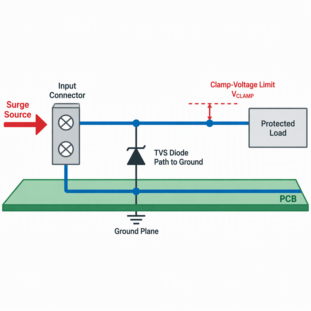
A TVS diode cannot be selected from clamp voltage alone; the surge waveform, source impedance, test level, coupling path, and pass/fail condition must be defined first.
Identify the equipment-level surge environment, such as the switching or lightning transient surge condition described by the applicable immunity test plan.
Record the waveform, test level, generator setup, coupling or decoupling network, line under test, and required operating state during and after the event.
Translate the protected circuit’s voltage limit into a maximum acceptable residual voltage at the node being protected, not only at an ideal diode terminal.
Keep direct lightning-current injection and insulation high-voltage withstand requirements outside the TVS selection assumption unless the product test plan explicitly includes them.
If the defined surge comes from an equipment immunity standard such as IEC 61000-4-5:2014, use that standard to frame the test method and limits, but do not treat it as proof that any single diode or supplier product is qualified.
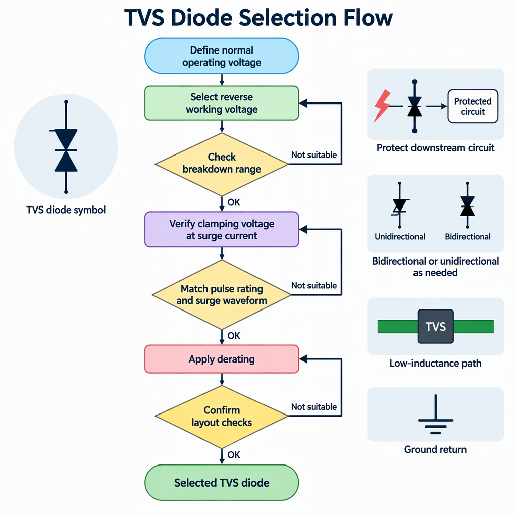
The selection chain is normal operating voltage to reverse working voltage, then breakdown behavior, then clamping voltage at the specified surge current and waveform.
Selection point | Buyer check | Why it matters |
|---|---|---|
Reverse working voltage | Choose a value above the circuit’s maximum normal voltage, including tolerance and steady-state variation. | The TVS should remain outside surge-protection conduction during normal operation so it does not become the normal current path. |
Breakdown voltage | Confirm the datasheet test current and breakdown range rather than reading a nominal value in isolation. | JESD210A is scoped to avalanche breakdown diode TVS terms, rating verification, and measurement methods, so stated test conditions are central to comparison. |
Clamping voltage | Compare clamp voltage only at the stated peak pulse current and waveform. | A lower-looking clamp value is not comparable if it was measured at a different current or pulse condition. |
Protected-node limit | Compare the selected device’s stated clamping condition with the downstream circuit’s voltage tolerance and the design margin required by the equipment. | The buyer is selecting a rated protection component for a defined circuit limit, not a voltage number in isolation. |
A TVS diode is a candidate only when its peak pulse rating is compared against the same surge waveform, current path, and measurement assumptions used for the design requirement.
Question | Acceptable screening approach | Common mistake to avoid |
|---|---|---|
Is the surge requirement equipment-level? | Tie the requirement to the specified test setup, recommended levels, and procedure. | Assuming a diode rating alone represents a complete equipment surge pass. |
Is the TVS rating measured under the same pulse shape? | Compare datasheet values under matching or clearly translatable waveform conditions. | Comparing peak pulse power numbers from different waveforms as if they were interchangeable. |
Does the clamp target hold at the defined current? | Check clamping voltage at the relevant peak pulse current, not only at a lower demonstration current. | Selecting by a clamp voltage line without checking its test current. |
Is repeated exposure part of the requirement? | Ask for the rating basis, stress count, and derating guidance before design release. | Treating a single-pulse value as a lifetime endurance statement. |
For procurement and quality review, keep the equipment immunity requirement and the component datasheet requirement separate: the former defines how the product is stressed, while the latter helps screen whether the protection component is plausible for that stress.
A TVS diode that meets a voltage target on paper can still be unsuitable if derating, package rating, or the implemented current path is outside the conditions used for its stated ratings.
Check the ambient and board temperature range against the device’s derating information before assuming the full pulse rating is available.
Confirm whether the package is rated for the required surge stress under the same waveform and temperature assumptions.
Review the datasheet measurement conditions for clamping voltage, peak pulse current, peak pulse power, and thermal derating before approving the part.
Keep package comparisons tied to stated ratings instead of assuming two packages are equivalent because their voltage values look similar.
Ask whether the supplier’s recommended land pattern and thermal assumptions match the board space available in the design.
For design review, request the relevant datasheet curves, rating definitions, and recommended use conditions rather than selecting by package name alone.
Polarity, capacitance, and package are application constraints: they must match the protected line’s normal voltage behavior, signal needs, mechanical space, and surge-rating requirement.
Use where the protected node has a defined polarity and the device’s rated behavior fits the DC rail or unipolar signal condition.
Use where the line normally swings positive and negative, or where the protection choice must address surge polarity in both directions.
For power inputs, prioritize voltage margin, surge-current rating, package rating, and thermal derating under the defined waveform.
For data or RF-related lines, add capacitance and leakage checks so the protection device does not disturb the interface.
For multi-line interfaces, check channel count, polarity, package, and per-line electrical limits before assuming a single-line TVS choice scales to the full interface.
For space-constrained boards, confirm that the smaller package still supports the required pulse stress under the same waveform and temperature assumptions.
Standards help define scope, terms, test methods, and rating context, but they do not automatically certify a supplier’s TVS diode for your product.
JESD210A is directly relevant when discussing avalanche breakdown diode transient voltage suppressors because its landing page identifies scope covering terms, definitions, rating verification, and measurement methods.
IEC 61000-4-5:2014 is useful for equipment-level surge immunity context, including test requirements, methods, levels, equipment, setups, and procedures.
IEC 60747-2:2025 is a rectifier-diode standard context source, so use it only for diode terminology and documentation scope that fits its rectifier-diode domain.
JESD66 covers thyristor surge protective devices used primarily in telecommunications, so it is a boundary reference when distinguishing TSPDs from avalanche TVS diodes.
Before design release, ask for the actual device datasheet, applicable test report, and qualification scope for the selected part; do not use a rectifier-diode or thyristor-protection standard as proof of TVS product qualification.
A useful TVS recommendation request should include the surge requirement, protected circuit limits, operating voltage, target clamp voltage, waveform, temperature range, package constraints, and approval evidence needed by quality or procurement.
State the surge standard or internal test method, including waveform, level, source impedance, coupling path, and pass/fail condition.
Provide maximum normal operating voltage, tolerances, expected steady-state variation, and the protected device’s voltage limit.
State the maximum acceptable clamping voltage at the protected node and identify the peak pulse current condition used for that limit.
List temperature range, board area, package preference, line count, signal speed, capacitance limit, leakage limit, and polarity requirement.
Request datasheet conditions for breakdown voltage, clamping voltage, peak pulse current or power, derating, and recommended layout or mounting assumptions.
For quality review, separate component evidence from final equipment surge-immunity evidence so responsibilities are clear.
If the requirement is unclear | Next buyer action |
|---|---|
Surge level or setup is not fixed | Confirm the applicable equipment test plan before requesting a final TVS part number. |
Clamp voltage target is lower than the available device behavior at the required current | Revisit system tolerance, request alternative protection options, or evaluate a staged protection architecture. |
Capacitance limit conflicts with surge capability | Prioritize by interface function and evaluate whether a lower-capacitance device, different package, or staged protection is needed. |
Select the TVS diode only after the surge condition, voltage margin, pulse rating, and implementation limits are all aligned under comparable test conditions.
For a defined surge and clamp-voltage target, start with the equipment stress and test setup. Then translate that requirement into component parameters, check datasheet conditions, and carry the same assumptions into RFQ, design review, and quality approval.
These questions help engineering, quality, and procurement keep TVS diode surge protection decisions tied to test conditions rather than isolated catalog values.
No. It should be selected above the maximum normal rail or signal voltage, including tolerance and expected steady-state variation, so the TVS does not conduct during normal operation.
No. Breakdown voltage describes avalanche conduction under stated measurement conditions, while clamping voltage is the limited voltage during a specified surge current condition.
Waveform matters because peak pulse current, peak pulse power, and clamp voltage are meaningful only when the test pulse shape and duration are comparable.
No. IEC 61000-4-5:2014 frames equipment surge-immunity testing, including methods and setups, but it does not by itself qualify a single TVS diode for every circuit.
Capacitance becomes critical on high-speed, RF, or precision signal lines where the protection device can load the interface or disturb the signal.
Not without checking pulse rating, derating, package rating, and stated test assumptions. A smaller package must still support the required surge stress under the defined condition.
Use rectifier-diode standards only within their stated rectifier-diode scope. They do not prove that an avalanche TVS diode product has passed your surge-protection requirement.

