
 English

Views: 0 Author: Site Editor Publish Time: 2026-11-16 Origin: Site


A Zener diode voltage regulation circuit is sized by confirming the required regulated voltage, the full input-voltage and load-current range, and then choosing a series resistor that keeps enough current through the shunt device while limiting power dissipation in both the diode and resistor.
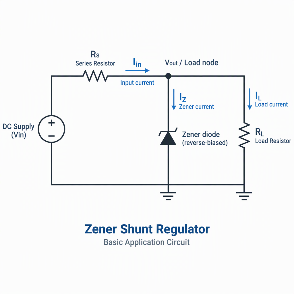
In a shunt regulator, the Zener-style reference is placed across the output node so that excess current is diverted through the shunt path while the load receives a regulated voltage.
The series resistor sets the available current from the input supply and must be evaluated across the highest and lowest expected supply conditions.
The Zener or shunt reference must receive enough bias current after load current is supplied, because shunt references require bias current in addition to expected load current.
The output node is useful for noncritical reference or regulation tasks, but accuracy, temperature coefficient, long-term stability and noise can limit a simple discrete Zener design.
Choose a simple Zener regulator when the load current is modest, the input range is known, and the design can tolerate the diode’s voltage tolerance, drift and noise; choose another topology when precision or efficiency dominates.
Design condition | Selection implication |
|---|---|
The input voltage can vary, but there is enough headroom above the required output voltage. | Evaluate a resistor-biased shunt regulator and check current at both input extremes. |
The regulated node is a noncritical reference or clamp where modest accuracy is acceptable. | A fixed Zener circuit may be a practical, simple option. |
Initial accuracy, temperature coefficient, long-term stability or noise are dominant requirements. | Consider a more precise voltage reference or regulator technology. |
The design needs an adjustable output above a reference threshold rather than a single fixed Zener voltage. | An adjustable shunt reference can set output voltage with external resistors. |
Do not select a Zener circuit from nominal voltage alone. Treat accuracy, temperature behavior and noise as selection criteria, not afterthoughts.
Size the series resistor from the input-voltage range and current requirement: it must feed the maximum load current and the minimum shunt bias current without exceeding device power limits at the highest input voltage.
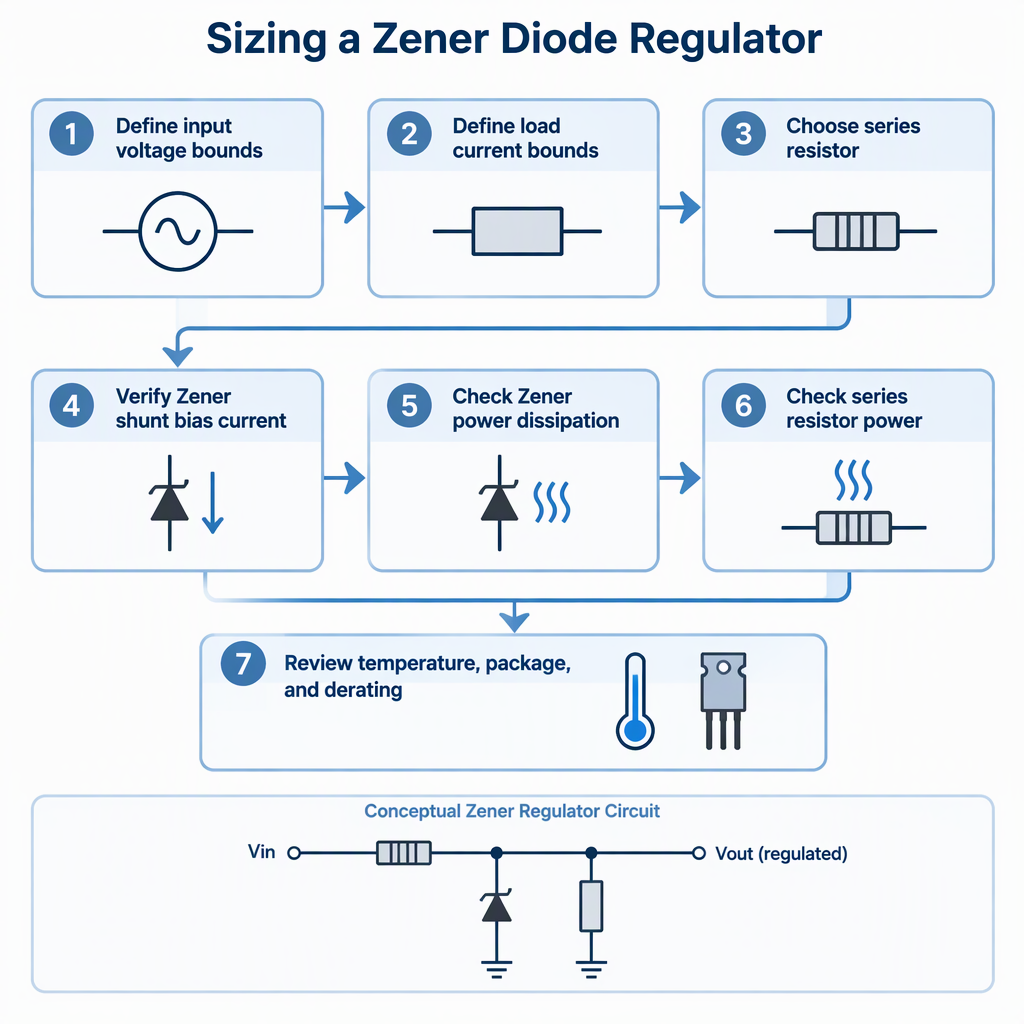
Define the regulated voltage target and the full input-voltage range seen by the circuit.
Define the minimum and maximum load current at the regulated node.
Confirm the shunt device bias current needed for regulation and add it to the expected load-current requirement.
Calculate the resistor current from the voltage dropped across the resistor: input voltage minus regulated voltage, divided by resistance.
Check the low-input case first, because it determines whether the shunt path still has enough bias current after the load is supplied.
Check the high-input and light-load case next, because it can drive the highest shunt current and highest power dissipation.
For an adjustable shunt reference, account for the supply and load-current bounds when calculating the shunt-reference resistor network.
A resistor value that works at one bench condition can fail at another. Use the minimum input, maximum load, maximum input and minimum load corners before releasing the circuit.
Before design release or sourcing, check shunt current, diode power, resistor power, load-current range and input-voltage extremes against the selected part’s datasheet limits.
Minimum input voltage with maximum load current still leaves enough current for the shunt element.
Maximum input voltage with minimum load current does not force excessive shunt current.
The resistor power rating covers the highest voltage drop and current combination.
The selected device’s voltage tolerance, noise and stability match the circuit’s accuracy requirement.
The operating temperature range is included in the accuracy review, not checked only at room temperature.
The circuit load is known well enough that the shunt regulator is not asked to absorb uncontrolled current variation.
Temperature, package and derating affect whether the calculated circuit remains stable in production, because reference accuracy is influenced by initial accuracy, temperature coefficient, long-term stability and noise.
Factor | Buyer check | Why it matters |
|---|---|---|
Temperature coefficient | Compare the expected operating temperature range with the reference or Zener temperature behavior. | Output voltage can shift as temperature changes. |
Package power handling | Check the highest shunt-current case and the resistor power case together. | Small packages can be limited by heat even when the nominal voltage is correct. |
Long-term stability | Review whether drift over time is acceptable for the regulated node. | Precision references may be needed when drift cannot be tolerated. |
Noise | Confirm whether the regulated node feeds a sensitive analog, measurement or reference input. | Simple Zener regulation may be unsuitable for low-noise requirements. |
If the application requires tight voltage accuracy over temperature and time, do not treat a fixed Zener diode as equivalent to a precision voltage reference.
Use standards only within their stated scope: IEC 60747-2:2025 covers specified rectifier-diode categories and related terminology, ratings, characteristics, measuring and test methods, tests and marking, not every voltage-regulator diode application.
The IEC 60747-2:2025 page identifies the document as “Semiconductor devices - Part 2: Discrete devices - Rectifier diodes” and states a scope covering generic rectifier, avalanche rectifier, fast-switching rectifier and Schottky barrier diodes.
For a Zener diode voltage regulation RFQ, ask the supplier for the applicable datasheet, test conditions and qualification documents for the exact part number instead of using a rectifier-diode standard as product proof.
Move beyond a fixed Zener when the design needs adjustable output voltage, tighter accuracy, better drift behavior or a wider controlled operating window.
Option | Best fit | Selection caution |
|---|---|---|
Fixed Zener shunt regulator | Noncritical reference or regulation nodes where simple circuitry is acceptable. | Check accuracy, drift, noise and power limits. |
Adjustable shunt reference | Outputs set with external resistors above a reference threshold, including adjustable shunt-reference designs. | Calculate resistor values across supply and load-current limits. |
Precision voltage reference | Applications where initial accuracy, temperature coefficient, long-term stability or noise dominate. | Review the full reference error budget, not only nominal voltage. |
For supplier evaluation, separate general company and product-category context from the exact Zener diode model, package, rating and test data needed for a design release.
The first-party homepage identifies the company in English as Dongguan Merry Electronic Co., Ltd. and describes broad semiconductor product categories including rectifier diode, Schottky diode, silicon carbide diode, transistor, power supply IC and resistor.
When sourcing a Zener regulator part, request the current model list, datasheet, package drawing, electrical test conditions and quality documents for the exact part number before treating any supplier as approved for the design.
A good RFQ for Zener diode voltage regulation gives the supplier the electrical corners and documentation needs, not just a nominal Zener voltage.
Target regulated voltage and acceptable tolerance at the load node.
Minimum and maximum input voltage at the regulator input.
Minimum, typical and maximum load current.
Calculated shunt-current range and worst-case diode power.
Operating temperature range, accuracy expectation, drift concern and noise sensitivity.
Required package, marking, datasheet, test conditions and supplier documentation for the exact part number.
A Zener regulator is selected by current and power corners first, then screened for accuracy, temperature behavior, package limits and sourcing documentation.
Start with input and load-current extremes, because they control resistor sizing and shunt current.
Use precision references or other regulators when drift, noise or tight accuracy dominates.
Before RFQ or approval, ask for exact part-number datasheets and test documentation rather than relying on broad supplier categories.
These buyer questions help confirm whether a Zener shunt circuit is suitable before component selection and procurement.
It is a shunt-regulation method in which a reverse-biased Zener-style device helps hold the output node near a target voltage while a series resistor limits current from the supply.
Choose it from the voltage dropped across the resistor and the current needed by both the load and shunt element, then verify the lowest-input and highest-input operating corners.
Avoid relying on a simple Zener when tight initial accuracy, low temperature drift, long-term stability or low noise are key performance requirements.
It is useful when the output must be set with external resistors over a defined range rather than chosen from a fixed Zener voltage.
Temperature can shift voltage behavior, while package and power dissipation determine whether the device can handle the calculated stress in the intended environment.
No. IEC 60747-2:2025 is scoped to stated rectifier-diode categories, so use it only within that scope and request part-specific documents for Zener regulator selection.
Include regulated voltage, input range, load-current range, current and power calculations, temperature range, package requirement and the documentation needed for the exact part number.

